Vince
Posts: 14
Joined: Fri Aug 26, 2016 8:22 am

Localised infil

Hi.
Ive been trying a few ways to print an aerofoil section for a wing. Two main methods:-
1. design the wing as solid and let S3d hollow it out with sparse infill
Image

2. design it as a 'shell' in CAD and print it 'as is'
Image

The problem with the second option is that S3d does not print the outer skin in one movement but jumps about between the bracing and therefore the surface is not great.

Method 1 produces a beautiful outside skin but any internal structure is not well supported. Notice I have put small slots and holes near the spar tube in an attempt to connect it to the outer skin. Also the infill adds another internal wall layer for about 70% of the perimeter, adding weight.
Image
Image
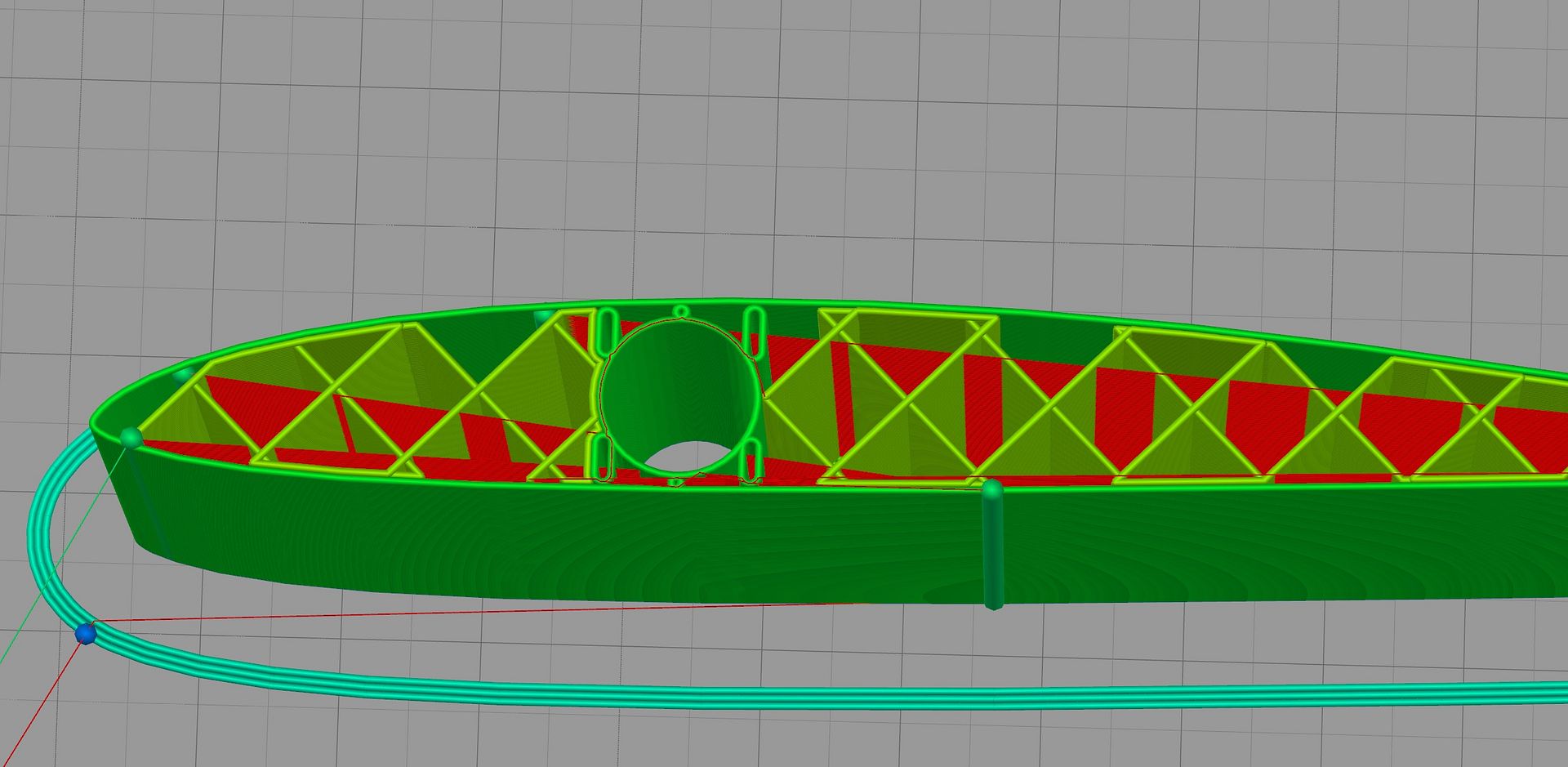
It would be great to be able to add localized internal support, similar how the external is done. I have tried various infills and fill % but the rectilinear seems to produce the best result, even if some of the infill lines are not well joined. Guess needs a bit of tweaking.
Any ideas welcome.
Heutinck
Posts: 77
Joined: Thu Mar 03, 2016 2:14 am

Re: Localised infil

just a stab in the dark here. would vase mode help?
C-line
Posts: 47
Joined: Wed Oct 08, 2014 12:52 pm

Re: Localised infil

By "localised infill" I assume you mean non-uniform infill, such as more dense in one area than another? If so, model your part in multiple sections according to where the infill is to be differentiated. Then import and align the separate STL files in S3D and set up processes for each with the desired infill.
Vince
Posts: 14
Joined: Fri Aug 26, 2016 8:22 am

Re: Localised infil

C-line, Ive tried that suggestion and while it kind of works for some parts its far from ideal. The main problem being accurate alignment of the multiple parts. I see that there is a discussion about aligning part origins with autodesk but its fairly lengthy process. S3d could benefit from allowing the mating of surfaces.

as far as Im aware vase mode is really only useful for single wall hollow parts but I expect to be corrected.
arhi
Posts: 480
Joined: Thu Oct 06, 2016 5:13 pm

Re: Localised infil

that is a pretty "simple mathematical object", why use slicer at all? why not write a small script that exports exactly what you want in g-code? you obviously know exactly what you want, and that should be fairly easy to output as G-code ?
gcodestat integrates with Simplify3D and allow you to
Calculate print time accurately (acceleration, max speed, junction deviation all taken into consideration)
Embed M117 codes into G-Code
Upload your G-Code directly to Octoprint
open source and unlicence
Vince
Posts: 14
Joined: Fri Aug 26, 2016 8:22 am

Re: Localised infil

Those pieces are simply parallel test parts. The real wing would change with span (z height) in size, shape, twist and cutouts. It would not be that simple (at least for me) to directly write my own gcode.
arhi
Posts: 480
Joined: Thu Oct 06, 2016 5:13 pm

Re: Localised infil

Vince wrote:Those pieces are simply parallel test parts. The real wing would change with span (z height) in size, shape, twist and cutouts. It would not be that simple (at least for me) to directly write my own gcode.
have you tried? it's actually easier the it sounds :D

it actually depends on how do you design the wings, if you are using some 3rd party plugins to get the wings shape then yes, but if you understand the airfoil and know math behind it (I don't) then the generation of g-code is more less identical as generation of the shape.. since there's almost nothing you have but the basic shape..

now if you do design them "visually" with some "tools" then yes g-code from that might be complex
gcodestat integrates with Simplify3D and allow you to
Calculate print time accurately (acceleration, max speed, junction deviation all taken into consideration)
Embed M117 codes into G-Code
Upload your G-Code directly to Octoprint
open source and unlicence
C-line
Posts: 47
Joined: Wed Oct 08, 2014 12:52 pm

Re: Localised infil

Vince wrote:C-line, Ive tried that suggestion and while it kind of works for some parts its far from ideal. The main problem being accurate alignment of the multiple parts. I see that there is a discussion about aligning part origins with autodesk but its fairly lengthy process. S3d could benefit from allowing the mating of surfaces.
Assuming the parts were created using a common orign (i.e., using the same origin defaults in your modeling program) they can be aligned automatically in S3D using the Edit>Align Selected Models command.
Vince
Posts: 14
Joined: Fri Aug 26, 2016 8:22 am

Re: Localised infil

Ive had a bit of spare time to try that suggestion on the sample wing. In Solidworks I split the airfoil into 3 parts with the middle part containing the spar tube.
Strangely, with all 3 parts imported in s3d the 'align model origins' worked on 2 parts but the trailing edge stubbornly kept aligning 0.5mm offset and requited manual alignment.
Anyway, if a single process was used the parts sliced as before with a continuous perimeter, as desired, however if 2 processes were used (one with dense infill) then they were treated as separate but close parts, every part having its own perimeter and therefore a non continuous outside skin.
I dont think there is a 'work around' to this so it looks like i will have to put tiny holes near the spar to effectivly increase the density in that area. Amyway, help much appreciated. Thanks.
Image
MHC
Posts: 12
Joined: Fri Jan 15, 2016 5:33 pm

Re: Localised infil

Vince,

Perhaps you could follow the same approach, but partition the model so that the outer skin is one single component, and the inner structures are separate components that, when aligned, will sit in the correct place inside the outer skin?

Mark

Return to “General Discussion and Tips”